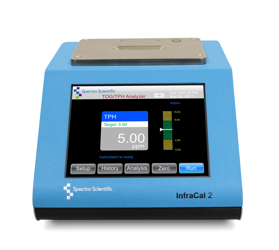
With over 4,000 oil and grease monitors in world-wide use today, InfraCal 2 Analyzers, originally developed by Wilks, have become a standard for the petrochemical and environmental industries. Wastewater professionals need a fast, rugged, easy to use option for monitoring wastewater discharge that doesn't cost them a fortune. This video shows how easy the InfraCal is to use.
Infrared Analysis Reduces Regulatory Fats, Oil and Grease (FOG) Testing Costs and Provides Fast Results
Ferrous Wear Metal Measurement Made Easy with the FerroCheck
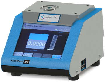
Historically, one of the most cost-effective indicators of machinery health has been the analysis of ferrous debris in oil. Such analysis utilizes the ferromagnetic properties of generated debris to perform the analysis. Since nearly all wear debris contains ferrous material (in particular iron), an abnormal increase in the amount of debris can be directly correlated to abnormal machinery conditions in the vast majority of cases. One type of ferrous debris analyzer is the magnetometer. The device works by sensing the disruption of a magnetic field that is generated due to the presence of magnetic particulates in the oil. Since the ferromagnetic properties of iron are well-known, the amount of disruption may be directly quantified to a certain amount (ppm) of iron. Devices such as the FerroCheck operate on this principle.
The ferrography technique was developed in the 1970s to overcome the large particle detection deficiencies of spectrometric oil analysis. It is a technique used for the separation of particles from fluids for microscopic examination and subsequent analysis. The name ferrography derives from the initial development of the methods to precipitate ferrous wear particles from engine lubricating oil. The original analytical ferrograph used a strong magnetic field gradient to separate wear particles from the used oil sample for subsequent microscope examination.
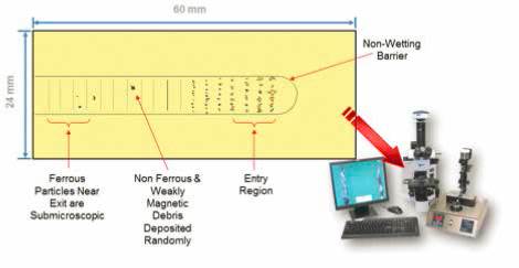
Figure 1: Example of a Ferrogram. On the lower right is an image
of the Spectro Scientific Thistle Tube Ferrography Lab including
ferrography slide maker, microscope and wear particle atlas (WPA)
software with reference pictures.
Since that time, a number of different instruments have been introduced such as the rotary particle depositor which also separates wear particles for microscopic examination along with other instruments which quantify the amount of ferrous wear debris in an oil sample. The primary instrument in ferrography is the analytical ferrograph which is used to prepare a ferrogram. A non-wetting barrier is painted on one surface of a microscope slide. This coating traps the fluid delivered by a peristaltic pump. In use, the slide is mounted at a slight horizontal angle, permitting the fluid to flow by gravity along the glass but within the barrier, where it finally is picked up by a drain tube.
The slide is mounted above two permanent magnets which are separated by an aluminum sheet. The poles of the magnets are counter posed. That is, where one magnet pole is considered north, the pole of the other magnet across the aluminum strip is south. Positioning the magnets in this way causes a strong magnetic field gradient to be created in the vertical direction above the aluminum strip. Magnetic particles in the fluid experience a strong downward force. These particles migrate through the fluid down to the glass surface, where they are deposited in strings perpendicular to the direction of fluid flow (Figure 1).
After all the fluid in a given sample has run across the slide, a fixer solution is passed over the slide to remove residual fluid. When the fixer has evaporated, the slide is ready for observation using the microscope. Ferrous particles are deposited on the slide according to size. The force acting on a particle is proportional to volume, but the viscous resistance of the suspending fluid is proportional to surface area. Therefore, for spheres, force increases with the cube of the diameter (volume) but resistance increases only with the square of the diameter (contact surface) [1].
The largest ferrous particles, therefore, are deposited at the entry region of the slide where the lubricating oil first touches down on the glass surface. At a position farther along the slide, all ferrous particles larger than a characteristic size already will have been precipitated. For non-ferrous particles, such as aluminum, brass, white metal, etc., precipitation will often occur because these materials are weakly magnetic. However, the deposition of these materials will be less size-selective. Consequently, large particles of nonferrous metal may be found anywhere along the length of the slide as also shown in Figure 1.
Figure 2: Example of cutting wear, severe sliding wear and
fatigue wear
Examination of the slide in a bichromatic microscope reveals details of size, shape, and number of particles. From this information the condition of oil-lubricated parts may be assessed [2]. Machines operating normally usually generate small flat particles at a slow steady rate. If the number of particles increases, and particularly if the ratio of large to small particles increases, we have an indication that a more severe mode of wear has begun. The generation of large severe wear particles signals the imminent failure of the wearing surface.
Different wear mechanisms each generate characteristic particles. Six regimes of wear have been identified with sliding wear. Miscellaneous shaped particles are associated with break-in wear. Small platelets are associated with normal rubbing wear. As operating parameters become more arduous, the metallic rubbing wear particles increase in size and become oxidized. Finally, just prior to failure, large, metallic, severe wear particles are produced.
Abrasive wear, analogous to a crude machining process, generates particles in the form of loops, spirals, and bent wires. Increase in the number and size of these particles shows that an abrasive wear mechanism is progressing rapidly.
In addition, two types of particles are associated with rolling mechanisms. These are fatigue chunks and laminar particles. Fatigue chunks represent material removed as rolling elements spall. Laminar particles, which are large, thin plates, result from material being passed through the rolling contact. Combined rolling and sliding, as in gears, produces scuffing particles and fatigue chunks. Determination of the composition of particles can establish their origin. The site of deposition, reflectivity, and color of particles aid in their identification. Figure 2 shows examples of abrasive wear, sliding wear and fatigue wear.
Ferrography can be useful to detect situations that are not obvious, such as water in oil as described below:
Water in Oil Analysis for Industrial and Turbine Oils with FluidScan
Water contamination in turbine and other industrial oils can be a very serious issue and water testing is always a part of any lubricant condition monitoring program. Turbine oils typically are formulated to have high thermal stability, oxidation resistance, and excellent water separation. Lubricants available specifically for gas turbines or steam turbines are designed with specific additive formulations, but there are also many oils that can work with all different types of turbines. Gas turbines have the tendency to build up sludge and varnish whereas steam turbines may experience oxidation, foaming, and sludge. However, a concern of all turbine systems is water contamination. Severe water contamination can cause changes in the oil’s viscosity, accelerated oxidation, additive depletion, and decreased bearing life. Turbine manufacturers typically recommend a warning alarm limit of <1000 ppm.
Bottles
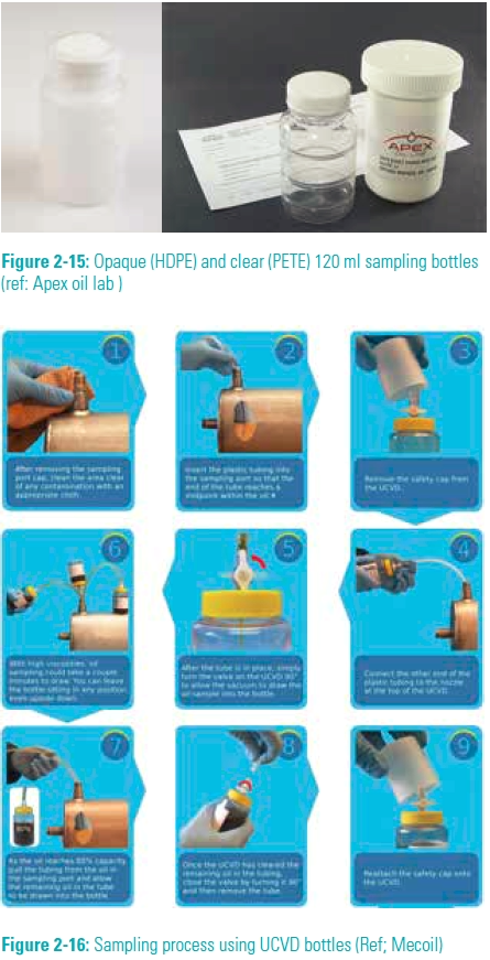
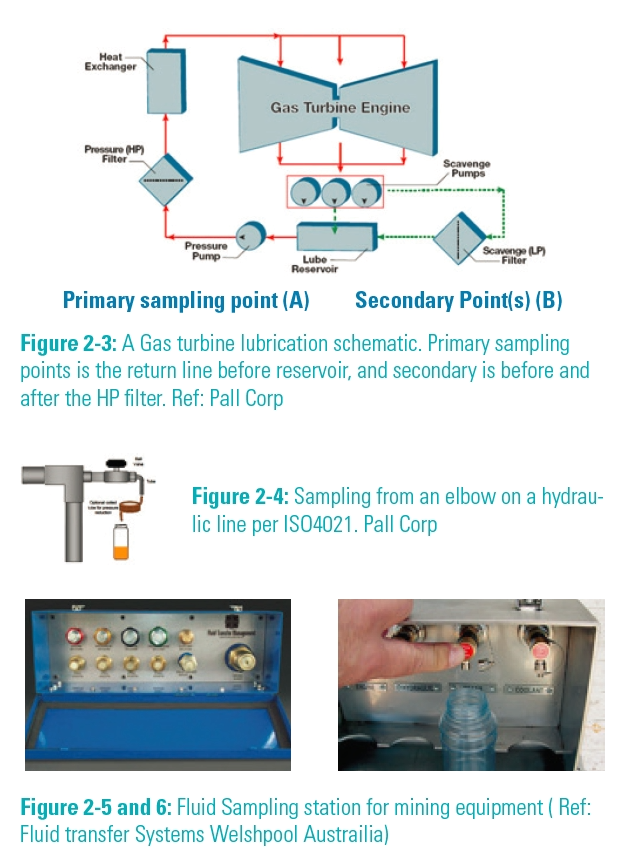
Sampling bottles come in many shapes and sizes. 120 ml (4 oz) HDPE (opaque) bottles have been the most common sampling bottle for many years. Many suppliers now provide clear PET, or PS bottles for oil sampling so end users can readily see debris or water in the sample, forcing a resample before sending it over to the testing area, or outside service provider.
Obtaining a representative oil sample from a closed loop lubrication system is essential to any good oil analysis program. As oil analysis programs become more standardized for routine monitoring, especially within equipment warranty support programs, equipment makers provide more sampling points on new equipment. These access sampling points make it easier for operators to quickly and easily take representative oil samples.
Automated Oil Particle Analysis Helps Prevent Gearbox Failures
The major issue for premature failure in wind turbine gearboxes is bearing failure, which leads to gearbox failure. A wind turbine gearbox will not survive if the oil is not clean and especially if the hard ferrous particles are not removed from around the bearings.
There are 5 common tests for glycol in engine oil. These include:
- IR Spectroscopy
- Atomic Emission Spectroscopy
- Blotter Test
- Schiffer's Reagent Method
- Gas Chromatography
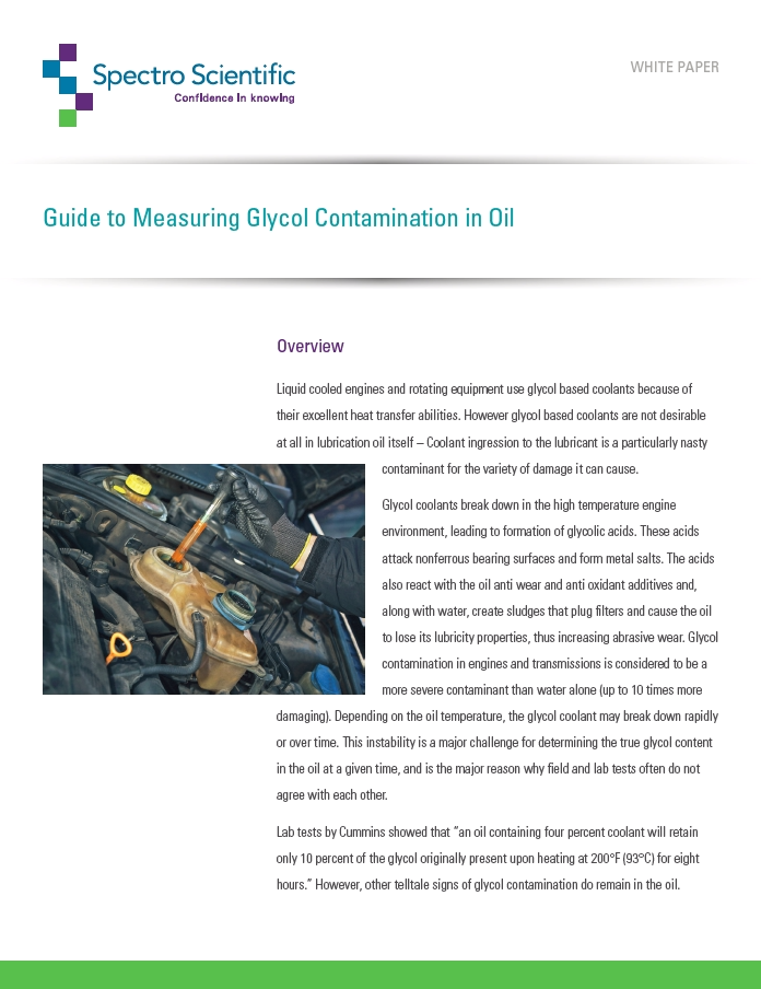
Liquid cooled engines and rotating equipment use glycol based coolants because of their excellent heat transfer abilities. However, glycol based coolants are not desirable at all in lubrication oil itself – Coolant ingression to the lubricant is a particularly nasty contaminant for the variety of damage it can cause. Glycol coolants break down in the high temperature engine environment, leading to formation of glycolic acids. These acids attack nonferrous bearing surfaces and form metal salts. The acids also react with the oil anti wear and anti oxidant additives and, along with water, create sludges that plug filters and cause the oil to lose its lubricity properties, thus increasing abrasive wear. Glycol contamination in engines and transmissions is considered to be a more severe contaminant than water alone (up to 10 times more damaging). Depending on the oil temperature, the glycol coolant may break down rapidly, or over time. This instability is a major challenge for determining the true glycol content in the oil at a given time, and is the major reason why field and lab tests often do not agree with each other.
Topics: Fleets
The Monitor
In this edition of The Monitor newsletter, we explore on-site oil analysis from several angles, including customer case studies, product highlights, and new educational materials.
See what’s new and exciting in the world of oil analysis.
On-site oil analysis pays off for fleet maintenance
Fleets use on-site oil analysis to reduce downtime and save money. This article highlights several different fleets including a municipal utilities fleet, a sheriff's fleet, a sanitation fleet and a city fleet, and how oil analysis benefits their maintenance activities. One of the biggest costs for the municipal utilities fleet was the labor cost associated with performing the oil changes. Safely extending oil change intervals saved them enough money to pay off the cost of the on-site oil analysis equipment in two years.
For the sheriff's fleet, the biggest cost was the cost of having law enforcement officers not out on the road doing their jobs. Bringing a vehicle in for an oil change often required paying officers overtime and took away from their more important activities. Extending oil change intervals saved on this cost.

