Introduction
This article is the first in a series to make a strong case for performing more and better testing of in service lubricants in order to replace unplanned repairs and unplanned downtime with planned repairs during scheduled time. In other words, this article is about using oil analysis to help improve reliability, planning and scheduling. More and better testing involves more lubricant sample points with better focus on large wear particle analysis.
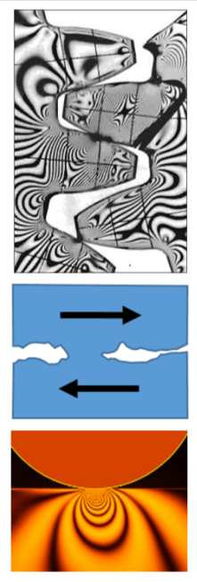 In service lubricant analysis is both proactive and predictive. Proactive measurement parameters such as particle count, water, glycol, viscosity, acid number focus on contamination control and lubricant fitness for use. Proactive lubricant chemistry and lubricant system contamination measurements, together with several other precision maintenance condition monitoring efforts, are effectively delivering long life and improved reliability.
Large wear debris analysis findings are predictive. This article is focused on nonintrusively measuring rate, mechanism, and severity of active abnormal wear. The goal here is to use active wear measurements to reduce unscheduled and unplanned repairs with planned and scheduled repairs. Predictive wear particle analysis supplements vibration analysis for gears and antifriction bearing failures due to rolling fatigue and severe sliding; supplements motion amplification for failures due to bending; and supplements turbomachinery protection systems for failures due to wiped plane bearings.
Large wear debris analysis includes metal (iron, copper, lead, and tin) particles in size ranges from five microns to hundreds of microns. Severe sliding and fatigue wear debris are essentially 100% large wear debris. Ferrous density and X-ray fluorescence are valuable tools to monitor severe sliding and fatigue worn gears, shafts, antifriction bearings, and plane bearings. Planning for equipment repairs and component replacement requires several months of advance notice. That is why our focus in this article is on the heavy hitting wear processes of severe sliding and fatigue.
Recommendations for planned repairs include the following. Study the repair histories and root cause failure analysis (RCFA) information. Use those insights and find ways to sample lubricants from gear, antifriction bearing, plane bearing, and other equipment components where adhesion and fatigue are likely. Begin doing more and better testing and analysis. Track progress toward reducing unplanned with planned repairs.
Abnormal Wear at its Worst
Severe sliding, rolling fatigue, and bending fatigue are failure mechanisms that exponentially shorten functional life of machine components. Damage from each mechanism is cumulative and progressive. Wear debris from each of these mechanisms carries evidence about the damaged component, the insults causing damage, and the stage or severity of failure progression.
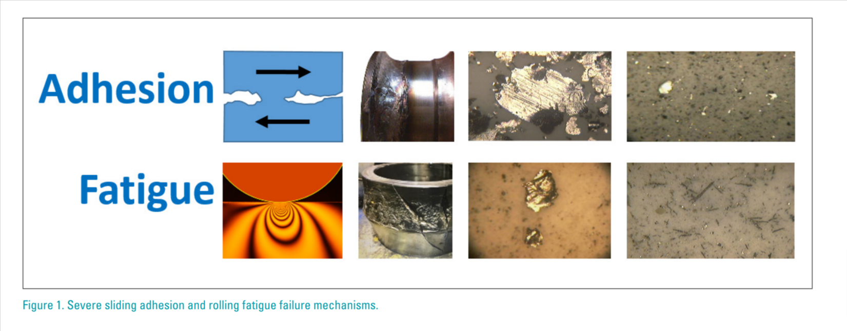
Component destruction from severe sliding wear is shown in images beside “Adhesion” in Figure 1. When a lubricant film between moving components is breached, the resulting metal-to-metal shear and friction produce intense heating, melting, and smearing. Metalto-metal sliding contact is caused by inadequate lubrication. In this case “inadequate” simply means the required hydrodynamic or elastohydrodynamic fluid film was breached while the machine was running under load. Common causes of inadequate lubrication include misapplication, slow speed, excess load, and low viscosity.
Component destruction from rolling fatigue, also called Hertzian fatigue, is shown in images beside “Fatigue” in Figure 1. Rolling fatigue is a subsurface work hardening process caused by highly loaded forceful rolling compression common for antifriction bearing rollers, raceways and for pitch lines of gear teeth. Bending fatigue (not shown in this figure) is a tension crack propagation process typically originating from a tight fillet or other stress concentration. Processes of adhesion, rolling fatigue, and bending fatigue are greatly accelerated by general corrosion, stress corrosion, galvanic corrosion, erosion corrosion, and spark erosion. To read more about these and other mechanisms refer to, “Why Equipment Fails and What You Can Do to Prevent It”, Machinery Lubrication, Nov-Dec 2019 (Part 1) & Jan-Feb 2022 (Part 2)
Severe Sliding and Fatigue Particles Range from 10 µm to Hundreds of Microns
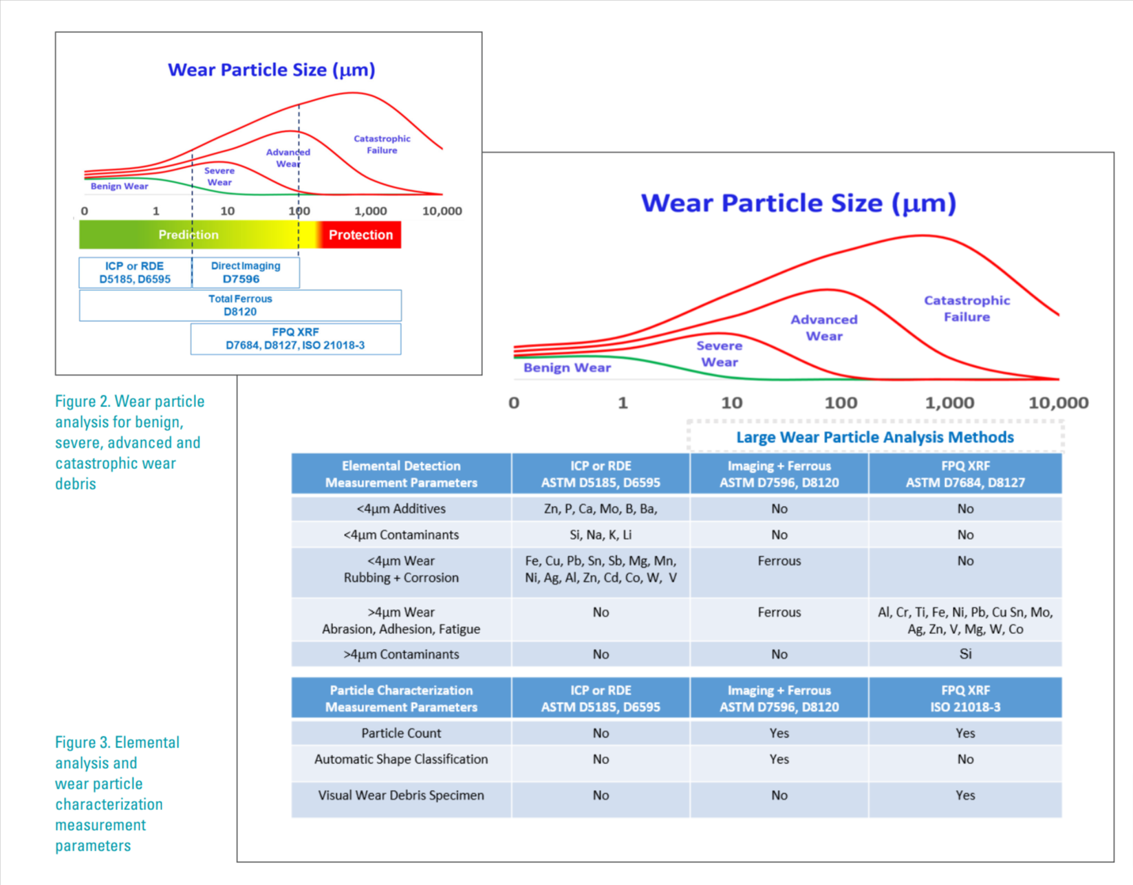
Adhesion and fatigue produce large wear debris in the severe, advanced, and catastrophic size ranges shown on Figures 2 and 3. These two figures illustrate wear particle size ranges called benign wear, severe wear, advanced wear, and catastrophic wear. See reference: “Oil Analysis vs. Microscopic Debris Analysis - When and Why to Choose” by Mark Smith, Analysts, Inc.
Adhesion and fatigue are abnormal wear mechanisms producing particles that are too large for optical emission spectroscopy methods. See reference: “Determining Fatigue Wear Using Wear Particle Analysis Tools”, by Dr. Jian Ding, Practicing Oil Analysis, 2003. Abnormal abrasion, adhesion and fatigue wear debris particles are large and contain base metal. Microspall particles range between 10 µm and 50 µm. Laminar particles and chunks range from 50 µm to several hundreds of microns. Optical emission spectroscopy is blind to large particles.
The green to yellow to red bar labeled “Prediction” and “Protection” on Figure 2 is intended to highlight the need to collect lubricant samples during the prediction interval so repairs can be planned and accomplished before reaching the catastrophic protection stage when unplanned repairs and unplanned downtime are unavoidable.
Several different instrument types are aligned in Figures 2 and 3 showing the instrument measurement capabilities for various wear particle size ranges.
Severe Sliding and Fatigue in Gears and Rolling Element Bearings
 Pumps, motors, compressors, gearboxes, fans, couplings, rolls, screens, and other rotating, reciprocating or articulating machines are prone to experience severe sliding adhesive wear, rolling fatigue wear, and fatigue cracking. It is common for incipient defects to progressively transition in successive stages. In this article successive stages of severity involve increasing size and increasing quantities of metal wear debris described as benign, severe, advanced, and then catastrophic wear debris.
Severe sliding adhesive wear involves abnormal metal-to-metal sliding contact between moving components. “Normal” for sliding motion between moving components typically involves a hydrodynamic lubrication film (approximately 100 µm thick) separating moving components. Localized adhesive wear often takes place when due to extreme loading, slow speed, absence of lubrication, low viscosity oil, or misapplication of lubrication. Severe sliding adhesive wear is also common when poorly lubricated rollers skid rather than roll because the rolling elastohydrodynamic lubricant film (approximately 1 µm thick) is breached.
Rolling fatigue wear involves cyclic rolling compression load such as between roller and raceway or between gear teeth in vicinity of the pitch line.
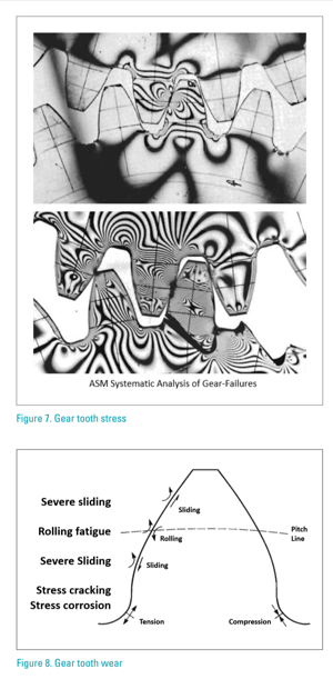
Figure 7 presents graphic representations of gear tooth stress patterns resulting from tooth to tooth load transfer.
The relative movements between adjacent gear teeth is shown in Figure 8. Normal rolling compression load transfer supported by an elastrohydronamic lubricant film (approximately 1 µm thick) is accomplished in vicinity of the tooth pitch lines. Above and below the pitch line normal movement between adjacent teeth involves sliding movement supported by a hydrodynamic lubricant film (approximately 100 µm thick).
Inadequate lubrication causes severe sliding wear, especially above the pitch line (addendum) and below the pitch line (dedendum). Inadequate gear lubrication is often caused by low oil, no oil, slow speed, extreme loading, low viscosity, and misapplication such no anti-wear extreme pressure (AW-EP) additive.
Rolling fatigue wear is common in vicinity of the pitch line where rolling compression loading is highest. Note that the lower right image in Figure 1 shows long, slender needleshape wear debris produced by rolling fatigue gear wear.
 Tensile stress cracking and stress corrosion cracking cause broken gear teeth, like what is shown in Figure 7 lower image. Root fillet fatigue fracture is the most common fatigue breakage mode. The crack originates at the root fillet on the tensile side of the tooth and slowly progress to complete fracture either along or across the tooth.
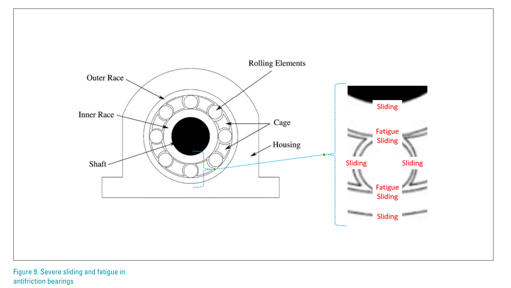
Severe sliding and rolling fatigue are often causes of antifriction bearing failures. From centerline out, Figure 9 shows a diagram of a roller bearing.
Looseness between inner race and shaft may cause severe sliding failure.
Inadequate lubrication may cause rollers to skid instead of roll in raceways.
Even with perfect elastohydrodynamic lubrication film (approximately 1 µm thick) highly loaded rolling elements and raceways will eventually experience fatigue wear.
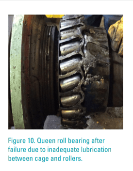
Relative motion between cage and rollers requires hydrodynamic lubrication film (approximately 100 µm thick). Figure 10 is a picture of a queen roll bearing that failed due to inadequate lubrication between cage and rollers.
Large Wear Debris Analysis for Gears, Shafts, Roller Bearings, and Plane Bearings
 The objective of this article is to avoid unplanned repairs and unplanned downtime. How is this accomplished? It is accomplished by more and better in-service lubricant testing and analysis. Place focus on sampling more lubricant sample points with better focus on large wear particle analysis.
Sampling in-service lubricants with focus on testing and analyzing large wear debris is a priority. For circulating oil lubricated machinery, always sample from the return line before it splashes into the oil compartment. Keep in mind that 5% of the oil is flowing through machine components bringing back valuable forensic large wear debris for analysis. When practical, collect live oil samples before 20:1 dilution. For non-circulating oil systems, follow active zone best practices for sampling.
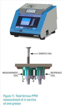
Sample and test in-service grease lubricants from bearings using ferrous PPM analyzer per ASTM D8120 (see Figure 11). Sample whenever it is practical. To get this practice underway and build confidence in the measurement for purpose of avoiding unplanned repairs, test abrasion and fatigue prone bearings whenever they are opened for maintenance, packing, or repair. Heavy duty diesel fleets only collect oil samples during oil change. So go ahead and get started doing similar testing for total ferrous PPM on grease lubricated bearings.
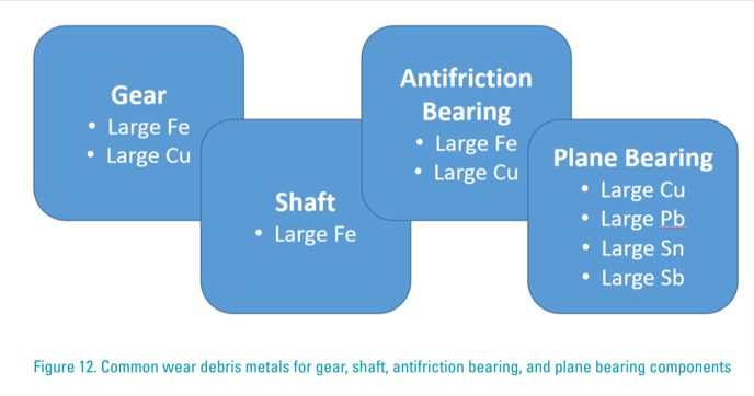
It is important to understand what metal elements are being generated by abnormal sliding and fatigue. To avoid unplanned repairs, we must sample, test, and analyze large wear debris. Those findings are then used to detect, trend, alarm and predict. Figure 12 identifies common metals for wear debris for gear, shaft, antifriction bearing, and plane bearing components. Large ferrous PPM is principal wear debris metal element for most industrial machinery such as gear, shaft, and roller bearings, and Large Copper PPM is second. Large wear debris from wiped plane bearings such as journals, bushings, very large motors, and turbomachinery, are likely to be “yellow metal” and “white metal” alloys that are primarily copper or lead or tin composition sometimes containing a small percentage of antimony.
Conclusion
The objective of this article is to avoid unplanned repairs and unplanned downtime. How is this accomplished? It is accomplished by more and better in-service lubricant testing and analysis using large wear debris analysis.
Pumps, motors, compressors, gearboxes, fans, couplings, rolls, screens, and other rotating or reciprocating or articulating machines are prone to experience severe sliding adhesive wear, rolling fatigue wear, and fatigue cracking. It is common for incipient defects to progressively transition in successive stages. In this article successive stages of severity involve increasing size and increasing quantities of metal wear debris described as benign, severe, advanced, and then catastrophic wear debris.
Abnormal wear at its worst. Severe sliding, rolling fatigue, and bending fatigue are very common failure mechanisms that exponentially shorten functional life of machine components. Damage is cumulative and progressive. Wear debris carries evidence about the damaged component, the insults causing damage, and the stage or severity of failure progression. Severe sliding and fatigue particles range from 10 µm to hundreds of microns.
Large wear debris analysis findings are predictive. This article is focused on nonintrusively measuring rate, mechanism, and severity of active abnormal wear. The goal here is to use active wear measurements to replace unscheduled and unplanned repairs with planned and scheduled repairs.
Predictive wear particle analysis supplements vibration analysis for gears and antifriction bearing failures due to rolling fatigue and severe sliding; it also supplements motion amplification for failures due to bending and supplements turbomachinery protection systems for failures due to wiped plane bearings.
Large wear debris analysis includes metal (iron, copper, lead, and tin) particles in size ranges from five microns to hundreds of microns. Severe sliding and fatigue wear debris are essentially 100% large wear debris. Direct imaging, ferrous density and X-ray fluorescence are valuable tools to monitor severe sliding and fatigue worn gears, shafts, antifriction bearings, and plane bearings.

Ray Garvey is a CLS certified materials engineer with decades of lubrication and oil analysis experience supporting AMETEK Spectro Scientific customers in industrial, fleet and laboratory markets worldwide.


