Retesting And Resampling Can Save Millions
Introduction
Power plants today face headwinds in delivering power to customers. Power suppliers must meet the “Three Rs” for power system reliability: resource adequacy (people, equipment, facilities, availability), system resiliency (ability to bounce back from disruption) and operational reliability (assets performing without unplanned downtime).1
Operational reliability involves maintaining and predicting critical asset downtime to avoid customer supply disruptions. Condition-based maintenance (CBM) tools such as oil analysis have been used to improve reliability of lubricated assets in power generation facilities for many years. New technologies, particularly in the area of onsite oil analysis, are available that transform how operators use and leverage the valuable information available with oil analysis. Classic examples of problems detected have been documented since CBM technologies have become mainstream. This is the first of the series of articles where we revisit case studies involving oil analysis and we examine how new technologies could solve the problems quicker and more cost effectively than originally reported.
This case study demonstrates how a costly shutdown was avoided when CBM technicians at a large US power plant used established fault tolerant and fault recoverable oil analysis and vibration analysis. They used the onsite condition-based maintenance (CBM) procedure outlined in Figure 1 to confidently continue normal operations, explain a false alarm, and take the appropriate corrective action. Prior to taking expensive maintenance actions
based on abnormal alarms, onsite technicians retest, resample, and explain their recommendations for taking appropriate corrective actions. Also, by examining the specifics of the case study, we identify examples where new technology could more clearly illuminate the most fundamental concern in this case history: Babbitt-type bearing wear debris.

Case History
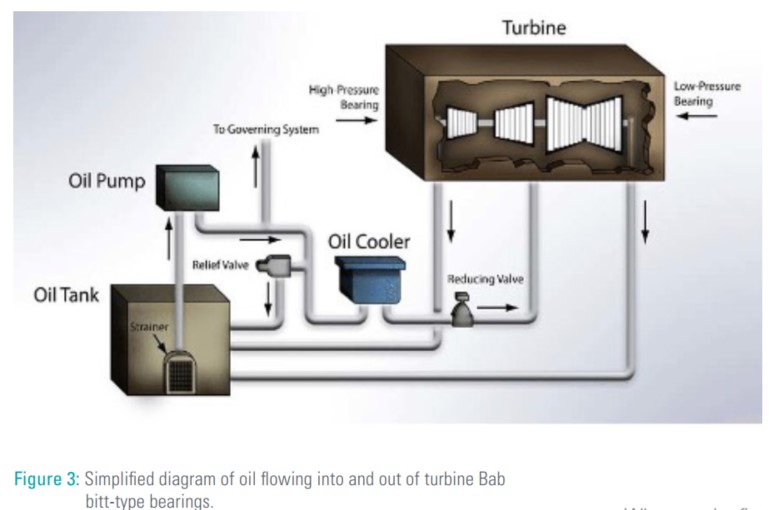
This case history originates from the Unit 1 steam-turbine/generator. The 10,000 gallon turbine oil tank lifts, lubricates, and cools an 800 MW steam-turbine/generator rotor. Lubricant flows through twelve Babbitt-type bearings. Ten of the twelve bearings weigh about a ton each. See Figures 2 and 3.


Power plant CBM technicians collected and tested oil samples from critical equipment monthly using the onsite MiniLab analyzer to evaluate oil chemistry, lubricant contamination, and large ferrous wear debris. One day, a routine oil analysis from Unit 1 turbine oil reported alarming wear and contamination due to large ferrous particles and high particle count in the oil. This unusual finding was a major concern, indicating potential bearing damage and potential contamination of the large oil compartment. Several questions came to mind: Is there a real problem? Did the sampling procedure introduce contamination? Is the onsite analyzer and operation working properly? Is there a real issue regarding turbine bearings or the lubricating system?
CBM vibration and oil analysts practiced their plant procedure outlined in Figure 1 when their routine periodic analysis findings potentially recommend expensive maintenance action. They would quickly retest and analyze the alarming measurements to verify proper operation and performance of their instruments. They would quickly collect, test, and analyze new measurements from the equipment using onsite tests. They would look for potential causes of abnormal findings. Then, considering initial results together with retested/resampled results along potential explanations, appropriate corrective actions were recommended.
This case history began when a routine periodic oil sample from Unit 1 steam-turbine/generator was tested and reported high wear and contamination alarms. Trend history for this sample point showed normal wear, contamination and chemistry, whereas this sample reported large ferrous particle debris, high particle counts, and normal viscosity and chemistry. Following the procedure, the onsite MiniLab operator immediately retested this oil sample. Retest results were the same as the first time tested. The MiniLab instrument and procedures were correct and repeatable. So the lubrication technician walked out to the Unit 1 turbine oil tank and collected a second sample
and brought it back to the onsite MiniLab. He tested a second sample, just like the first one, using the same instruments and procedures. This result was NOT alarming; it did NOT contain large ferrous particles and particle count values were normal and consistent with trend history.
Why was the first sample alarming with large ferrous wear particles and high particle count while the second sample was clean, dry, and fit for use? This facility was under regulatory control whereby any abnormality reported by a CBM tool would require immediate action to be taken up to and including taking the unit offline. This meant a root cause for the first sample results, while valid, needed to be determined.
Root Cause Investigation
CBM technicians inspected the vicinity and found that work had been done in the vicinity of the Unit 1 turbine oil tank during the last 30 days. They discovered that grinding had been done on the fifth floor above the sample point. They concluded that some metallic and dust debris was inadvertently captured in the sample container when the first sample lid was off while the sample was being collected.
Also, there had not been any recent issues or problems highlighted for Unit 1 steam-turbine/generator by turbine operators, vibration surveillance or protection systems. Abnormal alarming results from the first test and second test of this periodic oil sample were explained as false positive findings due to a contaminated sample container. Resample/retest results confirmed the lubrication system fit for on-going service and additional inspection findings validated the recommendation for uninterrupted operation of Unit 1 steam-turbine/generator. A turbine shutdown was avoided and a Corrective Action Report, (CAR) was implemented to upgrade standard oil sampling procedures.
Cost Avoidance
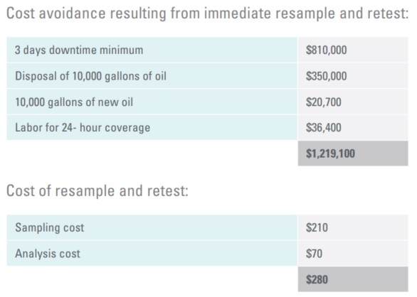
Without onsite oil analysis products, it would have taken another 3 days to obtain test results. The unit would have been taken offline while an investigation began. It would have taken another 3 days to get the results of the second sample and $270,000 per day is expensive downtime. That doesn’t include the cost of new oil, disposal of the used oil, and man-hours of labor.
If the first sample had been accurate, then the contaminated oil would have been circulating through the bearings for 3 or more days. This would likely have caused more damage and longer downtime.

Turbomachinery With Babbitt-Type Bearings:
In this case history, false positive wear and contamination alarms were tested and verified using the first sample collected. True negative findings were reported and confirmed by the second sample collected and immediately tested before expensive maintenance actions were initiated. These tests and retests were performed using ferrous density and particle counting measurements. Ferrous density measurements are ideally suited for monitoring abrasion, adhesion and fatigue in roller bearings and iron alloy gears.
It is very important to point out that ferrous density measurements are not well suited for monitoring Babbitt-type bearings primarily composed of copper, lead, tin, and antimony. Wear debris from iron alloy journals, roller bearings, and gears can be detected by ferromagnetic ferrous density measurement devices. The improved likelihood of true positive and true negative findings involving the twelve Babbitt-type bearings in this steam-turbine call for (1) active zone sampling from return line and (2) multi-element large wear debris analysis.
The new filtergram particle quantifier, with X-ray fluorescence (FPQ XRF) to performs pore blockage particle counting followed by energy dispersive X-ray fluorescence multi-elemental analysis, is now available for onsite oil analysis.
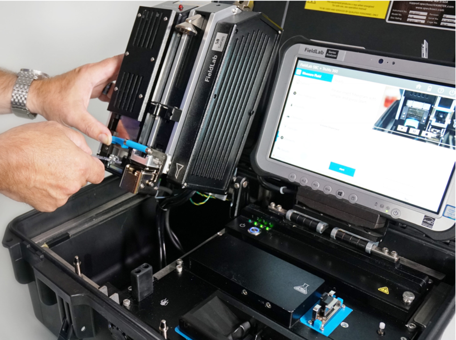
The FieldLab 58 onsite oil analyzer shown in Figure 4 provides a very detailed analysis of machine wear, system contamination and lubricant condition. This rich information, with built-in diagnostics providing real actionable findings, empowers onsite personnel to begin planning for repairs or design changes.
This FieldLab oil analyzer uses the MiniVisc and FluidScan tests to evaluate lubricant viscosity, chemistry, and fluid contamination. It also uses the FPQ filtergram process which serves three purposes: pore blockage particle counting, x-ray fluorescence wear debris analysis and specimen for viewing and further analysis as needed.
The FieldLab 58 XRF is ideally suited for turbines, generators, feed water pumps, other Babbitt bearing applications, sleeve bearings and worm drive gears. The XRF module non-destructively analyzes common wear debris Fe, Cu, Pb, Sn, Si, Al, Cr, Ti, Ni, Mg, Mn, Ag, V, W, Zn and Co wear debris from 4-micron to millimeter size ranges.

Figure 4: FieldLab 58 portable fluid analysis system reports kinematic viscosity, infrared chemistry and contamination, pore blockage particle count, and X-ray fluorescence multi-element large particle wear debris analysis.


