Practical Steps to Increase Your Site’s Ability to Detect
and Manage Abnormal Lubrication Events
There is a lot of discussion about artificial intelligence (AI), internet of things (IoT) and how these can be applied in all areas of reliability programs, particularly oil analysis. In this technology, many users struggle to understand and trust how alarms are set, maintained, and adapted to meet the changing conditions with lubricated mechanical equipment. All of these intelligence initiatives are ineffective if the data is not trustworthy.
Oil analysis alarms, and the application of them, have been developed and applied by laboratories and entities with large historical databases. As more equipment maintainers move to performing oil analysis onsite with the latest technologies, the alarms provided may not work to determine real faults. It is important to understand the basics of setting up alarms for your onsite program, and what is really needed for your site. And, most importantly — you can do it on your own schedule with the resources at hand.
This article outlines a five-part approach for setting, maintaining, and using meaningful oil analysis parameter alarms. This standardized alarm limit approach within onsite oil analysis is also relevant for AI and IoT processes.
Five Steps to Trustworthy Oil Analysis Alarm Limits 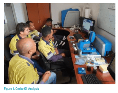
1. Lubrication personnel
2. Onsite advantage
3. Data quality
4. Recommended actions
5. Equipment profiles
Lubrication Personnel
The process of building and maintaining trustworthy oil analysis alarms begins with the lubrication team taking responsibility for oil analysis alarm limits. “Every successful oil analysis program I have observed has passionate technicians performing the work. And almost without exception, each includes some degree of onsite oil
analysis.” (Troyer, 2001)
The team responsible for setting and maintaining parameter alarm limits appropriate for the operating equipment
uses all of the following: pre-loaded alarm limit templates, industry standard limits, statistical limits per ASTM
D7720 or a similar approach, and trending limits.
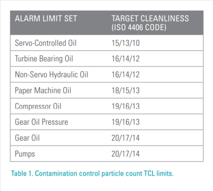
Table 1 provides example target cleanliness levels (TCLs) for setting particle count alarm limits. Particle Count
TCLs are usually easy to find for many equipment types in manuals or online OEM support, and a great first step.
Note that TCLs are lower for filtered than for unfiltered oils. We see confident maintenance teams make further
adjustments to contamination limits as appropriate for the operating environment.
Onsite Advantage
Unplanned repairs and downtime are ten times more expensive than planned repairs and downtime. An advantage for onsite oil analysis compared with offsite laboratory analysis involves collection and storage of valuable predictive maintenance expertise, and today there are more software systems available to capture this knowledge. There is no substitute for practiced firsthand experience, technical understanding, equipment manuals and specifications. Onsite technicians have ready access to databases that receive, accumulate, and report information pertinent to the equipment operating in that facility. This knowledge would otherwise have been lost when individuals change jobs. Today, fluid Intelligence software that drives onsite instruments, connected with ERP systems, or “Data Lake” connectivity provide important details such as:
- Lubrication information – lubricants, suppliers, compartments where fluids are stored and where they are used, target cleanliness levels for each storage and in-service fluid compartment.
- Oil compartment information – volume, fluid, level, add, drain, flush, fill, desiccant, and observations.
- Documented failure and repair history by item and by population – root cause failure analysis (RCFA), failure modes and effects analysis (FMEA), common failure mechanisms, and defect elimination strategy.
- Physical characteristics and interactions between machine components – bearings, rollers, journals, gears, couplings, cylinders, rings, shafts, belts, chains, engines, motors, and valves.
- Measurement point information – sampling location, method, frequency, analysis parameters and standard test methods for each one.
- Equipment operating characteristics – power, speed, primary, standby, operating, not operating, electrical, mechanical, hydraulic.
- Equipment criticality classification.
- Parameter trend history.
- Parameter dataset population for similar equipment under similar conditions.
- Alarm limit datasets by equipment population for wear, contamination, and chemistry parameters.
Data Quality
High confidence in oil analysis alarms is contingent on data quality. Consistent, repeatable and trendable measurement values are produced by well-trained operators running tests properly using calibrated instruments.
Excellent work processes are essential for good data quality. Wrong reference oil selection, poor sampling
techniques, incorrect test methods, incomplete records for time-on-oil, and mislabeled bottles all potentially lead
to false positive or false negative findings.
Here is some sage advice from technicians who have achieved good data quality needed for successful
lubrication programs.
Q. How do you get started with onsite oil analysis?
A. Start with 20 items of critical equipment. Implement excellent oil sampling and testing practices. Expand to 50 and then 100 samples/ month. Keep the oil clean, dry, fit for use, and look for evidence of wear debris in the oil. Use the particle counter, ferrous density measurements, and wear particle imaging.
Q. How often do you perform wear debris analysis or particle shape classification?
A. I do it on every sample. If I’m not doing shape classification, I am not looking at machine condition.
Q. How hard is it to recognize different shapes?
A. After you look at some samples with microscope and look at examples in the atlas, then you can tell whether a problem is fretting or fatigue or abrasion.
Q. What lead times are needed to achieve scheduled maintenance and repairs?
A. Planners and schedulers identify priority and severity for same week, next week or two weeks out. The planner
identifies parts, scaffolding, etc., to do each job. Shipping schedule estimates are unreliable, so we do not schedule until parts are in hand. Break-in repairs are planned.
Recommended Actions
An exceeded alarm value may provide a basis for making an observation, but this alone may not be sufficient
for making a diagnosis or for recommending an action.
The onsite maintenance team considers oil analysis findings, component maintenance history, visual observations, and information from other sources. Diagnosis and follow up recommendations may request resampling, retesting, further inspection, or other technology testing before taking expensive maintenance actions. Onsite answers enable these follow-up actions to be taken rapidly, a distinct advantage when investigating a problem. The response time alone is enough to justify onsite testing as a necessity.
For example, a paper machine, wire turning gear oil sample reported high alarms for wear and lubricant oxidation parameters. After inspecting the gearbox, the technician recommended diverting kidney loop oil supply to deliver extreme pressure (EP) gear oil directly to the nips for this turning gear. This recommended action improved torque performance, avoided failure, and the gear has operated normally for three years since.
Equipment Profiles
We mentioned earlier how “starter” oil analysis alarms, particularly for wear elements, are available to build on with onsite knowledge. These equipment profiles are a great way to manage equipment families as it is easy to assign globally with the latest software. Meaningful alarm limits derived from industry norms are applicable to all types of rotating and reciprocating equipment.
Take some time to ensure you have the right application (e.g., do not alarm a diesel engine with a gearbox profile) as this will likely produce false alarms, which lowers program confidence. Second, if you know the manufacturers’ details, do factor them in. To make this point, consider what results would be if a single set of alarm limits were made applicable to an equipment profile combining diesel engines from these two different manufactures: a first manufacturer’s alarm limits are Fe = 170 PPM, Cu = 30 PPM, Pb = 11; and a second manufacturer’s limits are Fe = 45 PPM, Cu = 15 PPM, Pb = 13. In this situation, personnel will not have confidence in alarm limits for the combined “diesel engine” equipment profile.
Conclusion
This five-part standardized approach can improve oil analysis alarm limits for detecting and managing abnormal lubrication events:
- A lubrication technician is responsible for setting and maintaining the site’s oil analysis alarm limits.
- An advantage for onsite oil analysis, compared with offsite laboratory analysis, involves availability of predictive maintenance knowledge and experience with operating equipment.
- Consistent, repeatable and trendable measurement values are produced by well-trained operators running tests properly using calibrated instruments.
- The onsite lubrication technician recommendations consider oil analysis findings, component maintenance history, visual observations, and information from other sources.
- Just as work processes are essential for excellent data quality, equipment profile grouping is necessary for meaningful alarm limits.


Ray Garvey and Daniel Walsh are CLS certified materials engineers with decades of lubrication and oil analysis experience supporting AMETEK Spectro Scientific customers in industrial, fleet and laboratory markets worldwide.