

Introduction
Comprehensive oil analysis requires sampling, testing and analyzing in-service industrial lubricants to evaluate the wear condition of machinery, the contamination condition of lubrication systems, and chemistry condition of the lubricants. This article intentionally focuses attention on analysis of large wear particles because the resulting analysis information enables informed users time for planned maintenance instead of surprise, reactive unplanned repairs.
Avoid Unplanned Repairs and Downtime
Unplanned repairs and downtime are normally more than ten times more expensive than planned repairs. For example, a planned repair of a roll bearing costing $1,800 translates to unplanned repair costs of $98,600. Planning takes time; in fact, it takes a lot of time. One way to create planning and scheduling time is through use of comprehensive oil analysis including large wear particle analysis.
Onsite analysis of wear, contamination and chemistry provides crucial findings and recommendations based on:
- Identified mechanisms of wear
- Trends of wear rates
- Determinations of root causes and severities
- Logical recommended actions with sufficient time for planned repairs
Common Mechanisms of Component Failures
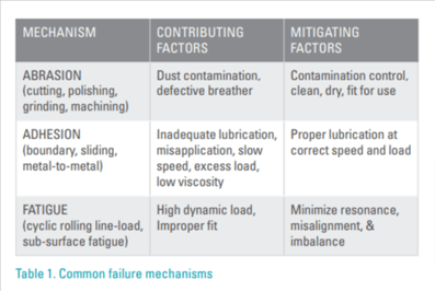
Abrasion, adhesion, and fatigue are three of the most common failure mechanisms by which components of industrial machinery progressively wear from incipient to catastrophic. To read more about these and other mechanisms refer to, “Why Equipment Fails and What You Can Do to Prevent It”, Machinery Lubrication, Nov-Dec 2019 (Part 1) & Jan-Feb 2022 (Part 2).
Table 1 outlines these mechanisms with contributing factors and mitigating factors for each.
Figure 1 depicts the mechanics for abrasion, adhesion, and fatigue mechanisms, presents extensively damaged example components, and presents images of large wear particles from each respective mechanism.
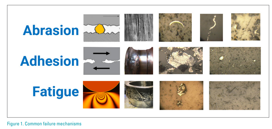
Catastrophic failure intervals are accelerated from decades to years to months under the influence of these multiple contributing factors. Corrosion and/or shaft current erosion affected morphology of bearing and gear components.
Wear Particle Size Ranges
Figure 3 illustrates wear particle size ranges for benign wear, severe wear, advanced wear, and catastrophic wear.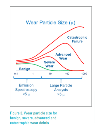 Please refer to: “Oil Analysis vs. Microscopic Debris Analysis - When and Why to Choose” by Mark Smith, Analysts, Inc.
Large Particle Analysis Techniques
A partial listing of large particle analysis methods includes automatic particle detector, large particle specimen, visual analysis, elemental analyzer, and a combination of these to characterize abnormal wear debris from in-service oil samples.
AUTOMATIC LARGE PARTICLE DETECTOR- Automatic particle counters rely either on filter pore blockage leading to flow or pressure decay, or on light
 extinction or light obscuration within a flowing sample of in-service lubricant particulates passing by a single pixel sensor. These non-discriminating counting methods are effective for contamination control, but not for wear debris analysis.
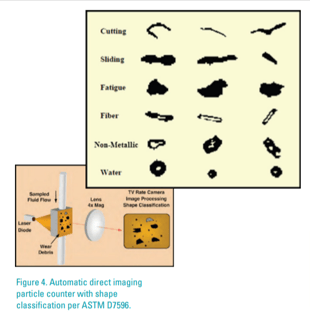
 - Automatic direct imaging particle counter with shape classification use light obscuration to count, size, shapeclassify, and shadow-image many particles per frame within a flowing sample of in-service lubricant passing by a focal plane array sensor. This discriminating particle counting method is effective for contamination control, for false positive count elimination and for distinguishing some aspects of large abrasive, adhesive, and fatigue wear debris. Particles ≥4 µm are counted, particles ≥20 µm are classified. See Figures 4 and 5.
- Automatic ferrous particle counters use ferromagnetic sensory techniques to distinguish, count, and size large ferrous wear debris within a flowing sample of in-service lubricant.
- Total ferrous PPM or other ferrous density index sensory techniques detect and quantify a ferromagnetic or diamagnetic or paramagnetic sensory response when a contained substance is presented to the sensory device.

LARGE PARTICLE EXTRACTION SPECIMEN
- Ferrogram. Glass microscope slide is used to separate large wear and other particulate substances from in-service lubricants using inclined plane or centrifugal body force to extract fluid and retain solid substance. Magnetic field lines of flux provide segregation of ferrous and non-ferrous particulates.
- Filter Rotrode. Vacuum filtration of in-service lubricant through semi-porous rotrode electrode accumulates large debris on outer diameter surface of a graphite electrode.
- Filtergram. Filter patch is used to segregate particulates larger than pore size from in-service fluid while smaller particulates pass through pores. Sequential filters and magnetic separators may be used to discriminate based on size or ferrous composition. Note that the filter pore blockage particle counters may produce a filtergram as described in ASTM D8127.
- Magnetic plug or magnetic chip detector (MCD tab). Some ferromagnetic debris is collected on a magnetic surface within an oil compartment or flowing fluid system. The plug is periodically removed and debris from the plug may be inspected and/or transferred for further inspection and analysis.
VISUAL ANALYSIS
- Large particle specimens may be examined visually by technicians using magnification to view particulate matter and compare what is seen to a wear particle atlas.
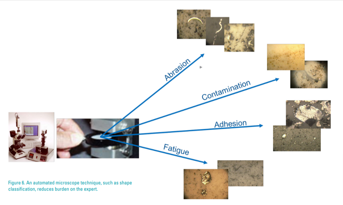
- Visual analysis may discern abrasion, adhesion, and fatigue mechanisms likely to have formed large wear particles (see Figures 1 and 6).
- Visual analysis with magnetic influence may help distinguish ferrous from non-ferrous.
ELEMENTAL ANALYSIS
- Optical emission spectroscopy (OES). A specimen preparation such as filter rotrode spectroscopy (FRS) is tested, typically in addition to a traditional rotrode spectroscopy sample test, for distinguishing PPM large particulates from fluid and small particulate measurements. See “New Rotrode Filter Spectroscopy Method”, Machinery Lubrication, 9/2006
- Scanning electron microscopy (SEM). A large particle separation specimen such as a magnetic chip detector (MCD tab) collects large wear debris. These separated particulates are examined using a SEM analysis technique such as energy dispersive x-ray. For example, see “Scanning Electron Microscopy for Wear Particle Identification”, Machinery Lubrication, 9/1999.
- X-ray Fluorescence (XRF). A filtergram or MCD tab or other large particle separation specimen is used to perform XRF elemental analysis of large wear particles, reporting PPM iron, copper, lead, silicon, and other elements. See U.S. Patent 9,791,386 B2 for an “integrated, portable sample analysis system and method.”
Comprehensive Onsite Oil Analysis
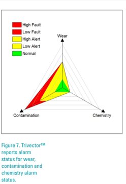
Comprehensive oil analysis requires sampling, testing and analyzing in-service industrial lubricants to evaluate the wear condition of machinery, the contamination condition of lubrication systems, and chemistry condition of the lubricants. Figure 7 graphically represents overall findings for predictive component wear condition, for proactive contamination condition and for proactive fluid chemistry condition.
Comprehensive onsite oil analysis provides several advantages for owners and maintainers of equipment assets.
- Immediate tests and immediate retests for wear, contamination and chemistry. Immediate re-test avoids likelihood of false positive or false negative findings due to misapplication, sampling, or testing issues. It is common practice for confirming results by resample and retest using on-site oil analysis before undertaking expensive maintenance and repairs.
- Test incoming lubricants. Best practices call for inspecting and testing incoming lubricants to assure target cleanliness levels and to avoid misapplication and cross contamination.
- Ownership and control of plant lubrication program is plant maintenance responsibility, not the vendors’ or contractors’ responsibilities. Motivated technicians actively participating in onsite oil analysis observe, notice, interpret and apply knowledge to improve lubrication.
- Find and fix contamination issues with validation of immediate on-site oil sampling and testing.
- Onsite oil analysis is flexible for growing programs. Start with 25 oil compartments, expand to 50, then to 100 and so forth. Set goals, monitor progress, share results and case histories.
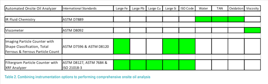
Table 2 below points out that fluid chemistry, contamination and viscosity may be monitored using methodology
such as ASTM D7889 infrared analysis and ASTMD8092 kinematic viscometer. In addition, this table suggests first
and second option methodologies for large wear particle analysis and particulate contamination control.
The first option methodology for large particle analysis per ASTM D7596 and ASTM D8120 uses direct imaging
particle counter with shape classification, total ferrous and ferrous particle count. This option measures PPM
total ferrous, shape classifies wear mechanisms and quantifies large ferrous and non-ferrous particulate debris.
The second option methodology for large particle analysis per ASTM D8127, ASTM D7684 and ISO21018-3 uses
filtergram particle counter with XRF elemental analysis. This option measures PPM ferrous, lead, copper and
silicon.
Oil Analysis Alarm Limits
 Alarm limits are thresholds delineating normal condition values from an abnormal condition values based on previous historic oil analysis parameter measurement experience with similar equipment operating under similar conditions and using similar test methods. ASTM D7720 provides an excellent guide for setting and adjusting oil analysis alarm limits.
According to the ASTM Standard Guideline (D7720), alarm limits for either Gaussian normal or causal datasets may be evaluated using a statistical cumulative distribution function (CDF). Also note that the nature of large wear debris measurement is causal and, therefore, must be evaluated using CDF to identify meaningful alarm level percentile thresholds.
It is very easy to construct a CDF and identify median, 94th percentile, 97th percentile, and 99th percentile parameter values from a dataset of similar equipment operating under similar conditions using one test method. By following these Guidelines, the lubrication technician is warned by an Alert indication to notice and prepare for action on a 3% portion of the overall set of equipment and is suggested to potentially authorize maintenance action on a 1% portion of the overall set.
The onsite lubrication technician should understand logical correlation between large wear debris measurement parameters and likely causes for alarming values. This understanding comes from experience with onsite equipment, onsite analysis, repair history, firsthand observation and collective experience.
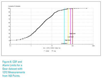
The following Figure 8 presents a CDF and alarm limits for Fe PPM measured using rotating disc spectroscopy
(RDS). This dataset includes 1272 measurements from 163 gearboxes operating under similar conditions. Alarm
limits for this equipment profile are 40 PPM low alert, 60 PPM high alert, 80 PPM low fault, 100 PPM high fault.
CDF shows that 4% of the measurement values are above alert level and <1% are above low fault.
Conclusion
This article intentionally focuses attention on analysis of large wear particles because the resulting analysis information enables informed users time for planned maintenance instead of surprise reactive unplanned repairs.
Large wear particle analysis is an essential practice for effective industrial oil analysis. These telltale metal fragments transport valuable information revealing wear process, wearing component identity, extent and severity of damage and failure progression.
A distinction is made between large (>5 µm) and small (<5 µm) wear debris analysis. Small wear debris tend to be mostly metal oxide whereas large wear debris normally include base metal, not just metallic oxide.
Large wear particle measurement and analysis methodologies are presented in this article, and best practices for evaluating and adjusting meaningful alarm limits for these measurement parameters are explained as well.

Ray Garvey is a CLS certified materials engineer with decades of lubrication and oil analysis experience supporting AMETEK Spectro Scientific customers in industrial, fleet and laboratory markets worldwide.

