
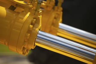
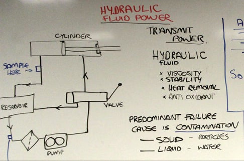
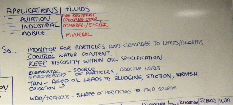
 Hydraulic systems are used in industrial, mobile and aviation applications to transmit power to operate equipment. They are incredibly efficient, compact, and lightweight relative to a mechanical equivalent. Hydraulic fluids transmit force in the system, and as such are carefully chosen by the system maker. Chemical stability, high flash and fire points, viscosity, and oxidation resistance are all valued, and as a result mineral and synthetic hydrocarbon fluids are selected for mobile and industrial systems, whereas functional chemicals such as phosphate esters are chosen for aviation and specialized industrial applications.
Monitoring hydraulics with oil analysis is the only way you can determine if the hydraulic fluid is impacting expected performance. Contamination is the predominant cause of failure, usually be dirt ingression or water contamination. Hydraulic systems all have filters and routine monitoring is performed not only to detect early signs of contamination and resulting wear, but also to determine how effective the filtration is.
 Tolerances in a hydraulic system are typically very tight. The clearances on servo valves are often on the order of 40-80 microns and the clearances on actuators can be as small as 10 microns, so particles larger than 4 microns can cause serious problems in hydraulic systems. There are several ISO codes, SAE guidelines and ASTM Methods devoted to measuring particles in hydraulic systems. Most of these code or methods bin particles by size and concentration.
Manufacturers of hydraulic systems will specify what ISO code one should use when evaluating system cleanliness. For instance they might recommend that ISO code 20/18/15 be applied to the pump in the hydraulic system, while ISO code 18/16/13 be used for the valve and actuator.
Water is the other contaminant that is often found in hydraulic systems. Water can cause corrosion and oxidize the hydraulic fluid. Typically water contamination should be kept below 2500 ppm.
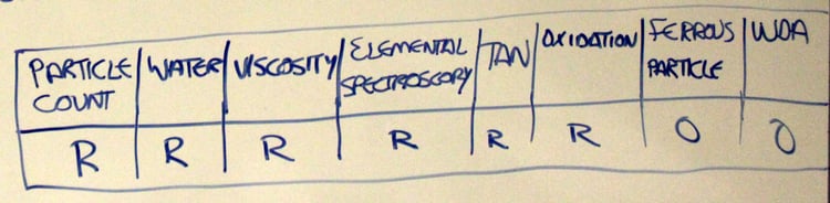
Key Parameters to Monitor
Particle Counting
The measure of cleanliness of a fluid, it is a critical test for hydraulic systems. Servo valves have very tight tolerances, and are susceptible to jamming with poorly filtered fluid. All OEMs specify cleanliness levels to ISO 4406, so frequent, routine particle counting is critical. When counts are elevated, understanding the cause is important. Newer technologies, such as LaserNet Fines, not only count particles and report to ISO 4406 or SAE AS 4059 , they also provide more detail to understand where the particles are coming from. Particle imaging enables the maintenance team to immediately see sand/dirt particles and also the level of ferrous debris that is contributing to the count. This level of detail enables smarter work orders to be developed, focusing on eliminating the root cause of the high counts.
 Water Contamination
Water is the most common liquid contaminant in power plants worldwide, and always needs to be monitored. Excessive water in a system destroys a lubricant's ability to separate opposing moving parts, allowing severe wear to occur with resulting high frictional heat. Water contamination should not exceed 0.25 % for most hydraulic systems. A number of new technologies are available to detect water contamination in lube oils, and on-site results correlate extremely well with laboratory techniques.
Kinematic Viscosity
Kinematic viscosity is the resistance of a fluid to flow under gravity. Viscosity is the most important lubricant physical property. Lubricants must have suitable flow characteristics to insure that an adequate supply reaches lubricated parts at different operating temperatures. The viscosities of lubricants vary depending on their classification or grade, as well as the degree of oxidation and contamination in service. Oil viscosity is expected to rise over time and use, and loss of viscosity is considered to be more serious than an increase. New technologies make it easy to measure kinematic viscosity- solvent free, low volume systems are available that combine ease of use with data logging capability.
Total Acid Number
Total Acid Number (TAN) refers to a titration method designed to indicate the relative acidity in a lubricant. The acid number is used as a guide to follow the oxidative degeneration of an oil in service and is frequently referred to on OEM equipment or lubricant supplier guides. Oil changes are often indicated when the TAN value reaches a predetermined level for a given lubricant and application. An abrupt rise in TAN would be indicative of abnormal operating conditions (e.g. overheating) that require investigation. .
Elemental Spectroscopy
Elemental spectroscopy is a technique for detecting and quantifying metallic elements in a used oil resulting from wear, contamination and additives. The oil sample is energized to make each element emit or absorb a quantifiable amount of energy, which indicates the elements concentration in the oil. The results reflect the concentration of all dissolved metals (from additive packages) and particulates. This test is the backbone for all on-site and off-site oil analysis tools, as it provides information on machine contamination and wear condition relatively quickly and accurately. Its major limitation is that its particle detection efficiency is poor for particles 5 microns in size or larger.
Oxidation by Infrared Analysis
Oxidation is a measure of the degradation byproducts in the hydraulic fluid. If oxidation becomes severe, the lubricant can corrode critical surfaces, and also deposit silt or lacquer deposits at servo valves. The greater the "oxidation number", the more oxidation is present. Conditions such as varnishing, sludge deposits, sticky valves, lacquering and filter plugging occur in systems with oxidation problems
WDA (Wear Debris Analysis/Analytical Ferrography)
WDA describes either a patch or an analytical technique that separates magnetic wear particles from the oil and deposits them on a glass slide known as a ferrogram. Microscopic examination of the slide or patch permits characterization of the wear mode and probable sources of wear in the machine. This technique is known as analytical ferrography. It is an excellent indicator of abnormal ferrous and non-ferrous wear, however it is usually only carried out by a trained analyst.
