
Measuring the Viscosity of an Oil
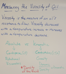
Viscosity is the measurement of an oil’s resistance to flow. Typically, we can expect viscosity to decrease with a temperature increase, and increase with a temperature decrease. Viscosity and temperature are considered to be inversely proportional. In oil analysis, viscosity is commonly measured using kinematic viscometers and reported in centistokes (cSt). Viscosity can also be measured using absolute (dynamic) viscosity techniques and reported in centipoise. Absolute techniques typically use rotational viscometers, whereas kinematic techniques will commonly use flow viscometers dependent on gravity. The two techniques are differentiated by fluid density.
 Important Factors
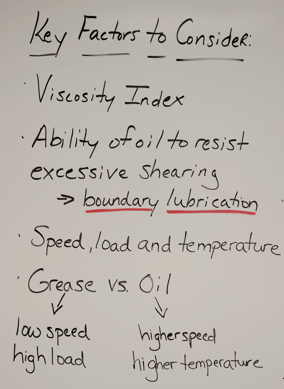
There are some important factors to consider when selecting the proper viscosity oil for your equipment: Viscosity Index (VI), shear stress conditions and component temperature are among the most important. Viscosity Index is a dimensionless value that quantifies relative changes in viscosity with changes in temperature. Oils with a higher VI tend to have less variation in viscosity with extreme temperature changes. Viscosity Index Improvers are a common way to improve the oil’s VI for mineral base oils. Higher VI oils can operate at a wider variety of temperatures and effectively reduce wear rates. Many synthetic base oils have naturally high VI values, but not all of them.
While effective in reducing temperature dependent viscosity changes, VI Improvers can be susceptible to mechanical shearing. Excessive shearing can lead to a decrease in viscosity values at higher temperatures, and cause the oil to be ineffective at creating the necessary fluid film at operating conditions. Excessive shearing can lead to boundary lubrication conditions, which occurs when two surfaces are no longer achieving full-fluid film (hydrodynamic or elastohydrodynamic). Boundary lubrication is sometimes unavoidable and in these cases we can use anti-wear and/or EP additives to protect the machine surface. Shock loading, continuous heavy loading, degraded or mixed lubricants, and extreme temperatures can also contribute to boundary lubrication conditions and lead to inadequate lubricant conditions. It is important to know if any of these conditions are occurring and make sure the proper oil (and additives) are selected to manage these issues.
Choosing the Right Viscosity
 Selecting the right viscosity is dependent on the speed, size, load, and temperature of the lubricated component. In some cases, this may mean selecting a grease rather than an oil. There are many tools and viscosity calculators available that can help in selecting the right viscosity for the component. In general, higher angular velocity (size and speed), higher temperature applications will typically require oil, whereas lower angular velocity applications can take advantage of the use of grease. Make sure to consult with the OEM to understand which lubricant is right for the equipment.
Causes of Viscosity Change
Viscosity is typically considered a lagging indicator test, meaning something occurred to cause a change in the oil’s viscosity. Most commonly, putting in the incorrect grade of oil is the reason for a significant and sudden viscosity change, but other root causes include contamination of water, fuel or other solvents or loss/shear of VI Improvers. Excessive moisture, heat, exposure to air and elevated metal concentrations (acting as metal catalysts) can lead to oxidation of the oil, which will also cause a change in the viscosity. In order to determine the root cause of viscosity changes, it is helpful to use instruments such as the FluidScan or Spectroil to trend changes in oil chemistry and elemental values.
 Alarm Limits
Setting alarm limits for viscosity can be done by first baselining the brand new oil. Baselining the oil is an important first step because ISO Grades typically have a +/- 5% cSt tolerance during the blending process. It’s important to know the starting point so condemning limits can be set accordingly. In general, +/- 5% is cautionary and +/- 10% is alarm. These limits can change accordingly. From my days in the oil lab, we sometimes went as high as +/- 20% as alarm, depending on the criticality and history of the component.
 Solutions
There are several ways to monitor viscosity including Kinematic Viscometers (u-tubes) per ASTM D445, Ametek Spectro Scientific’s MiniVisc 3000 per ASTM D8092, Visgages, Rheometers and Rotational Viscometers. Typically, ASTM D445 methods are run in a laboratory setting due to the glass capillary tubes and large constant temperature baths which are difficult to maintain in the field. Spectro’s MiniVisc 3000 is able to quickly perform kinematic viscosity with only a few drops of oil and the results are reported in centistokes per ASTM D8092. The small footprint and robust design allows for easy transport of the unit to virtually anywhere in the plant. If you have any questions regarding monitoring the viscosity of your oil, please contact Ametek Spectro Scientific so we can work with you to develop a solution that is right for you

References:
https://www.machinerylubrication.com/Read/429/viscosity-alarms-limits
https://www.machinerylubrication.com/Read/29144/oil-viscosity-drops
https://www.machinerylubrication.com/Read/29185/oil-viscosity-importance
https://www.bearingtips.com/bearing-lubrication-oil-vs-grease/
